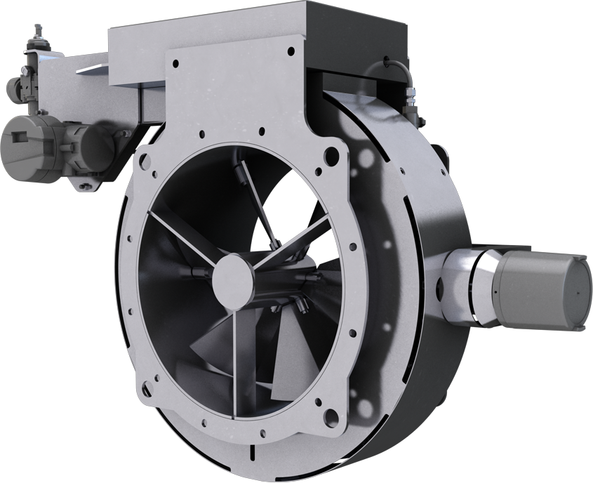
For manual operation, we offer a hand wheel driving a lead-screw & nut type mechanism. As an alternative, we can offer a locking quadrant, but this is only suitable for small dampers and IVCs with a diameter of less than 500 mm.
Any type of powered operator or servo can be specified. Actuators can be pneumatic, electric, hydraulic, or electro-hydraulic. A linear device such as a pneumatic ram is most commonly used on IVCs, but any semi-rotary actuator can be fitted.
A wide variety of instrumentation can befitted and tested in our works prior to delivery. Positioners for pneumatic actuators can respond to an analogue pneumatic signal in the range 3-15 psig. In standard mode, a 3 psig signal will result in the damper moving to the closed position, a 15 psig signal will cause the damper to move to the full open position, and a signal between the 3 psig and 15 psig limits will maintain the damper in a position between open and closed proportional the value of the signal relative to the 3-15 psig range.
However, safety considerations or process requirements sometimes dictate that the damper must move to the full open position in the event of the failure of the automatic controls. In this case, the positioner will be set in the Reverse Acting mode where the above motions are reversed.
Positioners for electric actuators are almost always driven by a current signal in the range 4-20 mA and again respond in a similar way to the pneumatic method described above.
Speak to the experts
Call today to book a meeting with our engineers
If switches are required and these are not part of the actuator, or if separate independent switches are required, we can fit a variety of types. These are usually operated by cams mounted on an extension to a blade shaft, protecting them from the excess over travel created by a badly adjusted striker, and providing the facility to have them open or close at any IVC blade angle.
In the event of a supply or signal failure, some applications call for the damper either to remain in its last position, or for it to move to a pre-determined position. This is readily achievable with pneumatic control systems by the addition of suitable control circuits (and air reservoirs if necessary).
Electric actuators will normally remain in position that they were when the power supply failed. Please note that the failure of the command signal will be interpreted by the positioner as a minimum signal (4 mA or 3 psig).


